|
(WORKING DRAWING SEEN ABOVE
IS DRAWN IN FIRST ANGLE PROJECTION) |
|
For more information regarding
drawing using orthographic projection -
click here. |
| |
|
| |
| |
PARTS LIST |
|
| |
|
|
|
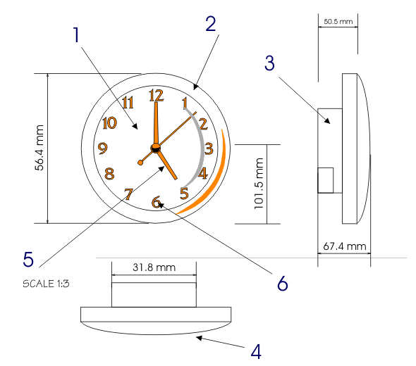
A ‘Parts List’ is a very important feature of the working
drawing as all the parts are listed, with measurements. The materials used
are also mentioned as well as the finish applied to the individual pieces.
Can you complete the parts list on the right? The working drawing clearly
shows a clock with an electronic mechanism. Also included are hands and
numbers. |
| |
|
|
|
PART No |
No OFF |
DESCRIPTION |
MATERIALS |
DIMENSIONS |
FINISH |
| 1 |
1 |
CLOCK FACE |
MDF |
|
RED PAINT |
| 2 |
1 |
CLOCK BACK |
PERSPEX |
Dia. 156mm x 20mm |
NONE |
| 3 |
1 |
MECHANISM |
|
|
NONE |
| 4 |
1 |
GLASS |
|
|
POLISH |
| 5 |
1 |
HANDS |
|
|
BLACK |
| 6 |
2 |
NUMBERS |
|
|
RED |
|
| |
|
|
|
Try to complete the parts list above - you may need to
estimate some measurements |
| |
|
|
| |
|
|
|
FURTHER INFORMATION |
| |
|
|
|
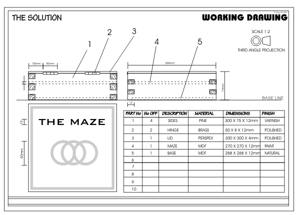
The example shown below has a back view, side view and plan view of a pine
box with a perspex lid. The box contains an educational toy.. The front view
is not needed because it is plain, with no detail. The back view has hinges
and consequently it is important that it is drawn. The working drawing (seen
below) is accurate and detailed so that a suitably skilled person could
manufacture the design from the information shown. |
1.
The working drawing should be precise and drawn to a scale. The drawing
opposite is half the size of the solution, the scale is 1:2. If the drawing
was a 3rd the size of the original then the scale would be 1:3.
2. Usually there are at least six dimensions
but you can add as many as you feel are required in order that the precise
size of your design can be determined by anyone reading the drawing.
3. Use a 2H pencil or a fine black pen for the
final outline, as the drawing will then stand out.
4. Draw the measurements (dimensions) very
carefully. Some example dimensions are shown below. They should be drawn
with a sharp 2H pencil. |
|
|
|
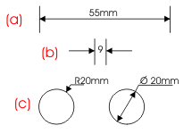
The arrows and the written measurement should be dark and
the rest of each dimension should be faint. Dimensions are normally drawn as
shown in (a) although dimensions under 9mm should be drawn as shown in (b).
Diameters and radii are drawn as shown in (c).
5. A parts list should be included. This gives
details such as overall dimensions, materials and finishes of each part.
6. Usually a working drawing is drawn in 3rd
angle projection, add the symbol to the drawing. |
| |
|
|
| |
|
|
| |
|
SUGGESTIONS |
|
A. Consider carefully the
type of views you need to draw (front, side, plan etc...) and draw a rough
version.
B. Number the parts in order, so that the
numbers are in sequence.
C. Use a T-square and set squares to help you
draw the proper version of the working drawing.
D. Add six dimensions, or more if necessary.
E. Do not fall behind in your work as you may
find it difficult to catch up. |
| |
|
CLICK HERE FOR DRAWING AND SHADING
TECHNIQUES INDEX PAGE |
| |
|
CLICK HERE FOR DESIGN PROCESS INDEX
PAGE |
| |
|
|
|
| |
|
|
| |
|
|
| |
|
|