| CLICK HERE FOR INDEX PAGE | |
| PROGRAMMING YOUR MICROCONTROLLER CIRCUIT | |
| V. Ryan © 2007 | |
|
When designing a programmable circuit such as a PICAXE circuit, it is a good idea to draw a flowchart explaining how you would like the circuit to work. This will help you understand and explain how inputs and outputs are to be linked to components such as switches , motors LEDs etc.... Each stage of the programme is drawn inside a box. The shape of each box is important as it determines whether it acts as an output, input or a process (sample see below). |
|
 |
|
|
Crocodile Technology and other software can be used to construct a PICAXE-08 based circuit. It can then be programmed using the flowcharting option within the software. The resulting circuit and programme can be tested on screen. This means that both the circuit and programme can be perfected before the circuit is exported to Real PCB software and manufactured as a Printed Circuit Board. |
|
| CLICK HERE FOR MORE DETAIL ON PROGRAMMING | |
|
|
|
|
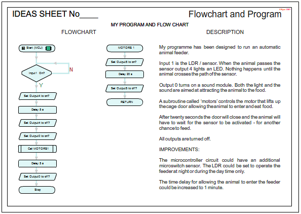
A sample layout to a design sheet is shown below. The flowchart is normally drawn on the left hand side with a simple explanation of each stage on the right. Once a description of each stage has been completed adding a paragraph or list of improvements to the way the circuit could operate will improve the overall grade. |
|
 |
|
|
|
|
| CLICK HERE FOR DESIGN PROCESS INDEX PAGE | |