| CLICK HERE FOR INDEX PAGE | |
| BREADBOARDS | |
| V. Ryan © 2002-2022 | |
|
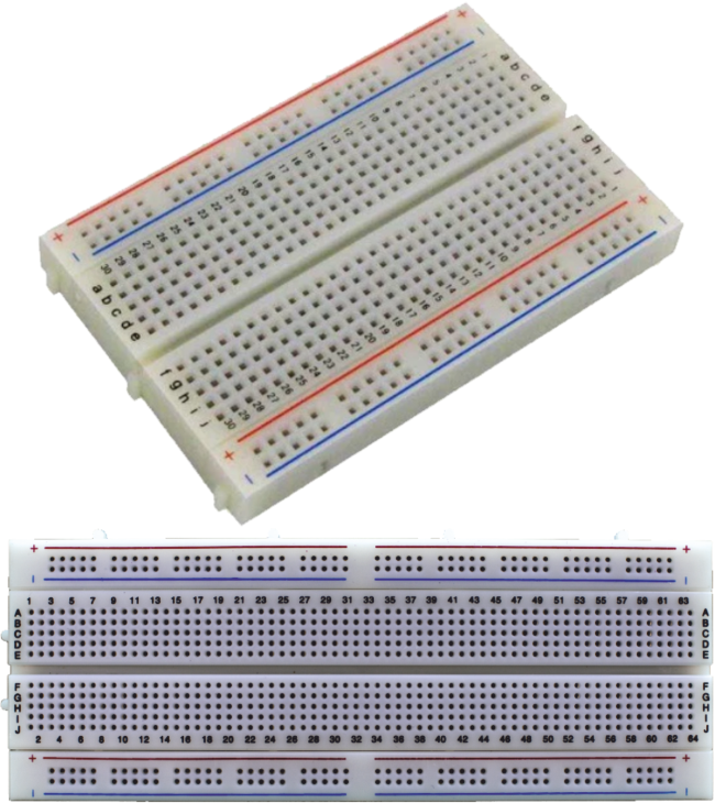
Breadboards are used to test circuits. Wires and
components are simply pushed into the holes to form a completed circuit
and power can be applied. One of the main advantages of using a
breadboard is that the components are not soldered and if they are
positioned incorrectly they can be moved easily to a new position on the
board. |
|
|
|
|
|
|
The red lines on diagram 2 show how some vertical columns and horizontal rows are internally connected. When power is applied to the breadboard current flows along these internal connections. |
|
Diagram 3 shows how a 380 ohm resistor and an LED are setup on a breadboard. When a 9 volt battery is attached the LED lights. Try replacing the resistor with a higher value such as a 680 ohm resistor. The resistance will be greater and the LED should shine less bright. |
|
| SAMPLE BREADBOARDS FOR ELECTRONICS | |
 |
|
|
|
|