| CLICK HERE FOR INDEX PAGE | |
| MORE FORCES IN ACTION | |
| V. Ryan © 2002 - 2023 | |
| PDF FILE - CLICK HERE FOR PRINTABLE WORKSHEET | |
| CLICK HERE FOR POWERPOINT VERSION OF WORKSHEET | |
|
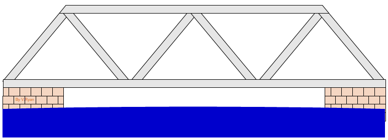
The bridge below is a common type called a Box Girder Bridge. These are usually made of steel with all the members (parts) welded, bolted or held together with rivets. Usually they are manufactured in a factory and transported to the site and dropped into position by a large crane. The triangular shapes give the bridge immense strength and for short spans this type of bridge is ideal. |
|
|
|
|
|
|
|
|
Triangulation distributes the weight of any vehicle or pedestrian crossing the bridge. The weight is distributed through all the members and so the bridge can cope with large weights. This type of bridge is favoured by the British Army. The Royal Engineers have transportable bridges like the one above that can be dismantled and transported anywhere in the world and reassembled. They are bolted together and are semi-permanent structures. See work on the Mostar Bridge. See work on the Mostar Bridge. |
|
|
|
|
|
When a vehicle crosses the bridge each member experiences some type of force. The diagram shows that the member that the car rests on is under tensile force (in tension) as it stretches under the weight of the car. As the bridge bends, the top member is compress (under a compressive force). |
|
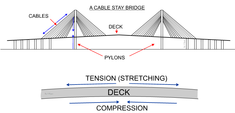
| The Cable Stay bridge drawn below is typical of many modern bridges. Forces are exerted on all the major parts, such as the deck, cables and pylons. The cables are in tension, as they stretch due to the weight of the deck. The pylons are in compression, as the weight of the cables and deck compress them. The deck is under both compression and tension (See diagram below bridge). The top surface of the deck tends to be in tension and the lower surface is under compression. | |
 |
|
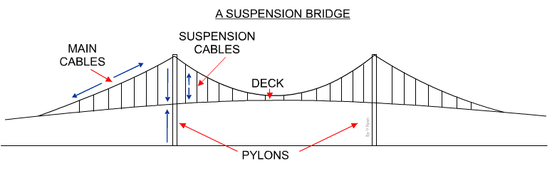
| The suspension bridge shown below, is the type of bridge found all over the world. The major parts are under pressure from compressive and tensile forces. The pylons are in compression, due to the enormous weight of the cables and deck. The main cables are in tension, due to the ‘stretching’ forces applied to them. They stretch from bank to bank and hold the pylons in position, stopping them moving/swaying too much. Also, the main cables secure the suspension cables and deck, an immense weight. The suspension cables are in tension, as they are being stretched by the weight of the deck. The deck of the suspension bridge is under the same forces as that of the cable stay bridge (see diagram above). | |
 |
|
|
1. Draw a diagram that shows the forces the supporting pieces (triangles) are under ? HINT: make a model from art straws and sellotape. This may help you see the forces in action as you add weights to the top. |
|
|
|
|