| CLICK HERE FOR INDEX PAGE |
| WORM GEARS |
| V. Ryan © 2002 - 2017 |
 |
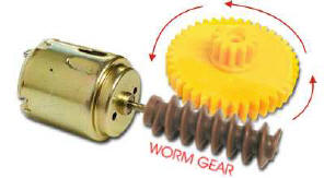
| The arrangement of gears seen above is called a worm and worm wheel. The worm, which in this example is brown in colour, only has one tooth but it is like a screw thread. The worm wheel, coloured yellow, is like a normal gear wheel or spur gear. The worm always drives the worm wheel round, it is never the opposite way round as the system tends to lock and jam. |
 |
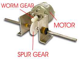
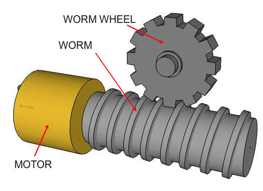
| The pictures below show the typical set up of worm gear systems as seen in school projects. As the worm revolves the wormwheel (spur gear) also revolves but the rotary motion is transmitted through a ninety degree angle. |