|
The circuit below is a version of the project board that can be made in a school workshop with PCB equipment. The components are clearly labelled. The INPUTS are on the left-hand side of the PCB and the OUTPUTS are to the right. Up to five inputs can be connected as well as eight outputs. |
|
|
|
|
|
|
|
|
The printed circuit board above has been set up with
a single input, the micro-switch. There are two outputs, both are LEDs.
The reset button should be pressed to start the program. The PIC
microcontoller integrated circuit has been programmed to react when the
microswitch, connected to input 0 has been pressed. As it is pressed,
the signal created is detected by the program stored within the PIC
microcontroller which lights the LEDs. |
|
|
|
The diagram opposite shows the track side of the PCB. The PCB is ready for drilling and then the components can be soldered in position. |
|
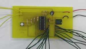
A photograph of an actual PIC microcontroller PCB circuit is seen opposite. The yellow wires are inputs ( up to five inputs can be used). Red and black wires are the positive and negative connect to a power source. The remaining wires are the positive and negative outputs. Can you identify the reset button ? |
 |
|
|
|