| PDF FILE - CLICK HERE FOR PRINTABLE WORKSHEET | |
|
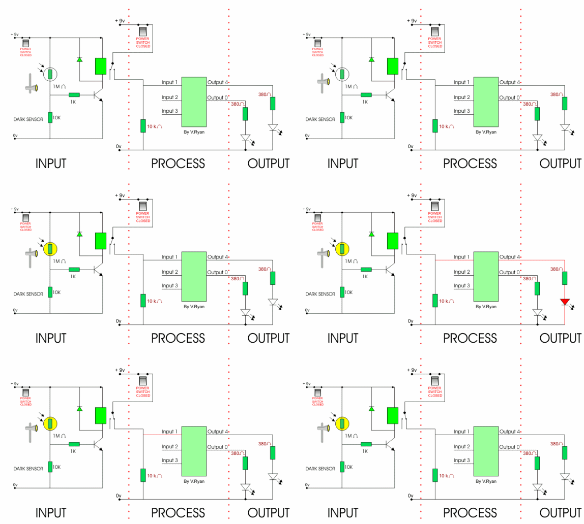
The circuit below is the same as the first PICAXE-08 circuit with the exception that a dark sensor circuit replaces the ordinary switch. Crocodile Technology software can be used to test the circuit before it is made with real components. The LEDs are outputs. Almost all circuits can be divided into INPUT, PROCESS and OUTPUT. These are clearly identified below. |
|
|
|
|
|
The circuit above has a simple light sensor in the
place of a push switch or pressure pad. When the light level rises, the
resistance in the LDR falls and this eventually allows current to flow
into the base of the transistor, energising the relay. |
|
|
|
|
|
|
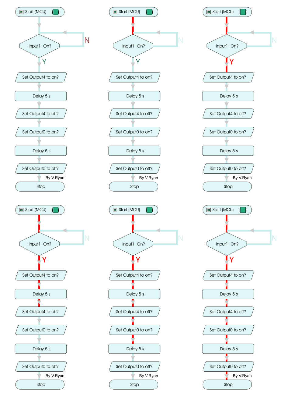
1. A START box is selected from the menu and placed in the working area. |
|
2. A decision box, called a ‘Test Input’ is connected to the start box. The text in the centre of the box is changed so that Input 1 is continually tested for activation. If input 1 is activated the programme moves down to the next line of the programme (the next process box). If Input 1 is not activated, the decision box continues to check for any change. |
|
|
3. This process box (called Set Output) switches on Output 4, which in the case of the circuit above turns on an LED. |
|
|
4. The Delay Box is set to 5 seconds and causes the programme to stay at this point for that time. |
|
|
5. Output 4 is then switched off. This has the effect of turning off the LED. |
|
|
6. Output 0 is then switched on, turning on the LED controlled by it. |
|
|
7. Output 0 is kept on for 5 seconds and consequently the LED stays on. |
|
|
8. Output 0 is turned off and, as a result, the LED. |
|
|
9. A Stop box is always placed at the end of a flowchart. The programme comes to an end. |
|
|
|
|
|
|
Crocodile Technology Software allows the translation
of the flowchart into BASIC programming language. This is extremely
useful if the programmer / circuit designer normally uses BASIC to
programme the PICAXE-08 and other PICAXE ICs. |
|
|
|


