Complete the circuit below to show how the control of the motor can be achieved.
| CLICK HERE FOR INDEX PAGE |
| SYSTEMS PREPARATION QUESTIONS 2007 - 4 |
| V. Ryan © 2007-2017 |
| PDF FILE - CLICK HERE FOR PRINTABLE WORKSHEET |
| As part of a GCSE project a student has designed a barrier system for a crossing. The specification drawn up by the student says - As a train approaches the crossing it breaks a light beam and the barrier is lowered, stopping cars and pedestrians. When the train has passed, the barrier should lift allowing cars and pedestrians to cross the railway line safely. |
|
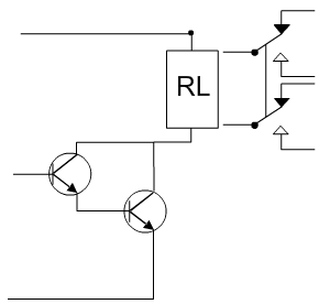
| The student’s prototype control circuit can be seen below. |
|
| 1. Name component ‘A’: ____________________________ |
| ANSWER |
| Name component 'A': Light Dependent Resistor. |
| 2. Give one reason why the circuit shown above will not meet the specification. |
| ANSWER |
| As the train passes the sensor the barrier will lower. However, the moment the train goes beyond the sensor the barrier will begin to rise. This means that it is possible that a car could cross the track and be hit by the train. There is no time delay holding the barrier in the lowered position. |
| 3. Write a modification that would solve the problem with the specification |
| ANSWER |
| A timer circuit such as a 555 circuit will hold the barrier in the lowered position until the train has passes the barrier |
| 4. Why is a darlington pair positioned between the sensor and the relay? |
| ANSWER |
| The darlington pair amplifies the current (signal) from the sensor to the relay ensuring that the current is high enough to energise the relay, turning on the motor that raises and lowers the barrier. |
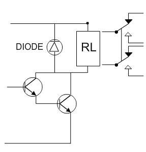
| 5. The darlington pair circuit has been tested but it regularly fails. Draw a modification on the circuit diagram below that will ensure that the circuit works without problems. |
|
| ANSWER |
|
| 6. Explain how your modification works. |
| ANSWER |
| The diode protects sensitive components such as the transistors from back E.M.F. When a current to a relay is removed the relay can emit current stored in its coils. This can be sent the wrong way round the circuit damaging components. The diode operates like a one way valve preventing this from happening. |
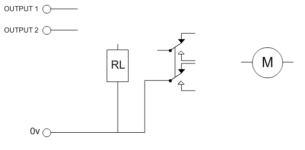
| 7. The student has decided to use a PIC microcontroller to
control the motor that raises and lowers the barrier. The student uses
outputs 1 and 2 to control the motor. Output 1 will turn the motor on and
off. Output 2 changes the direction of the motor. Complete the circuit below to show how the control of the motor can be achieved. |
|
|
| ANSWER |
| 8. The student decides to use one of the inputs to detect when the barrier has completely opened. |
| Name a suitable sensor: ____________________________________ |
| ANSWER |
| Name a suitable sensor: Microswitch |
| 9. Explain how the sensor would be used. |
| ANSWER |
| The microswitch will be positioned so that when the barrier is fully raised it is pressed. The micrositch will be connected to an input of the microcontroller circuit. The microcontoller will detect when the microswitch is pressed and keep the barrier raised until a train is detected. |
| CLICK HERE FOR ELECTRONICS INDEX PAGE |
|
|