| CLICK HERE FOR INDEX PAGE | |
| AND GATE LOGIC CIRCUIT | |
| V. Ryan © 2004 - 2009 | |
|
PDF FILE - CLICK HERE FOR PRINTABLE WORKSHEET BASED ON EXERCISE BELOW |
|
|
Below is a simple AND gate logic circuit designed for a dog. The dog’s owner is very concerned that when he is at work he can gain entrance to the kennel he has made. The kennel is situated outside. However, recently a cat has been entering the kennel and eating the dogs food. The owner has fitted an electronic device that is activated when the dog passes close to a light / dark sensor and presses a hidden pressure pad. Once this has been completed successfully, a motor opens the kennel door. |
|
|
1. The prototype circuit is built from a kit of modules eg. a light/dark sensor module, an AND gate etc... However, the circuit has failed. Clearly identify the module that is likely to be the cause of the failure. |
|
|
|
|
| 2. Why is it likely that this part of the circuit will fail? | |
| In the space below, draw the circuit built from modules, with a replacement module which makes it much more likely that the circuit will work successfully. Label the new module. | |
|
|
|
| 3. Why is the new module likely to be successful? | |
|
4. The prototype circuit made from modules such as a light/dark sensor and AND gate module etc... has be converted into a circuit diagram. This is shown below. However, four key components are missing. Complete the diagram by adding the four correct symbols. |
|
|
|
|
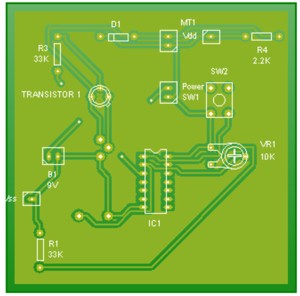
| 5. The complete circuit diagram has been converted to a PCB layout, shown below. However, two key components are missing. They are still to be soldered into position. Draw the missing components in position. Label the components. | |
|
|
|
|
6. Explain why it may be advisable to use a low voltage (transformer) to operate the circuit and motor. |
|
| CLICK HERE FOR ELECTRONICS INDEX PAGE | |
|
|
|