| |
| CLICK HERE FOR INDEX PAGE |
| |
| MODULAR ELECTRONICS SOFTWARE - 3 |
| |
| V. Ryan © 2004 |
| |
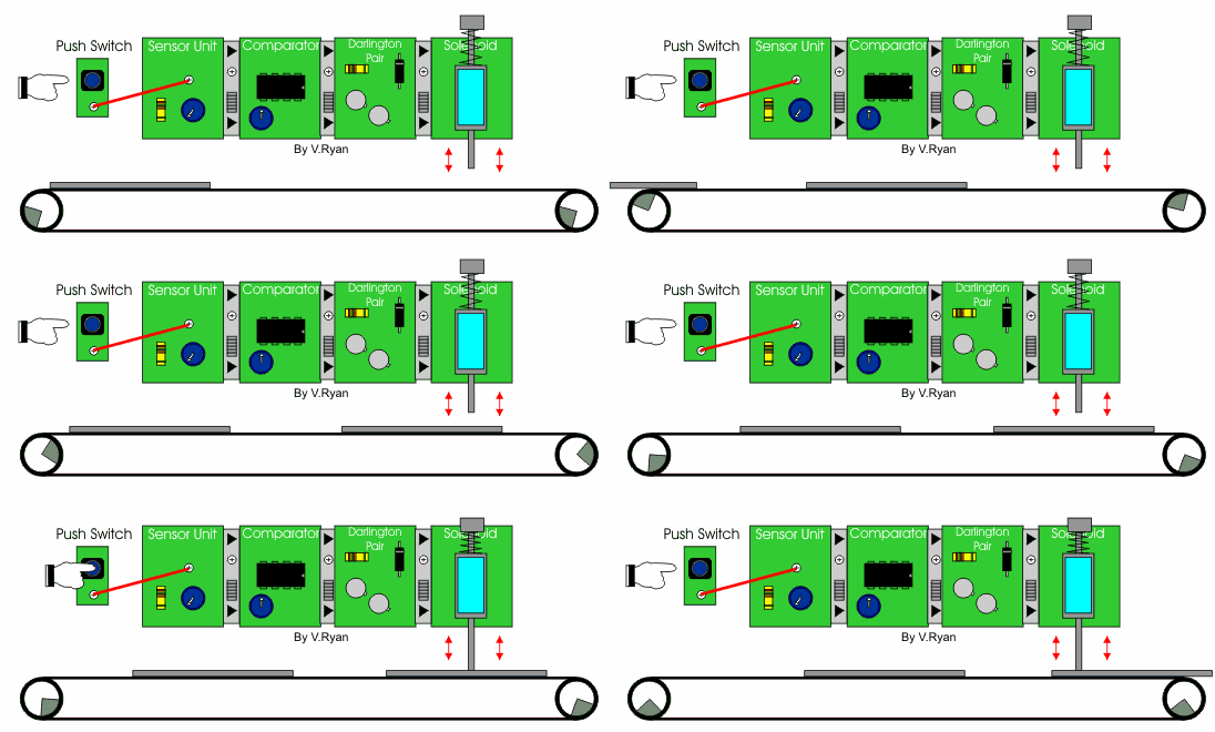
| 1. The diagram below shows a modular circuit and a
conveyor belt system. The circuit has a push switch which, when pressed,
causes a solenoid to punch a hole in a piece of card. The card travels
across the conveyor belt, is punched and then falls into a basket at the
end of the belt. |
| |
 |
| |
| When the push switch is pressed, the sensor unit
outputs current to the comparator. The comparator detects this change
and outputs current to the darlington pair. The darlington pair
amplifies the current driving the solenoid. |
| |
|
|
| |
| 2. Below is a system designed to
monitor the temperature of a car radiator. When the radiator temperature
becomes too high the voltage from the temperature sensor and sensor unit
changes. The comparator detects this change in voltage and activates the
transducer. The transducer driver provides enough power for the motor to
operate, cooling the car radiator. |
| |
 |
| |
| The modular circuit below is almost the same as the one above. However,
this time the transducer driver has been replaced with a darlington pair
module. The effect is the same. The darlington pair module amplifies the
current so that the motor can be powered. |
| |
 |
| |
| If the darlington pair is replaced with a transistor module (composed of
one transistor) - what would you expect to happen? |
| |
|
|
| |
 |
| |
| The single transistor does not amplify the current to the motor. As a
result the motor does not ‘spin’. Control Studio software allows
experimentation, without the need to build a real circuit using actual
components. It saves time and money as components are not wasted. |
| |
| CLICK HERE FOR ELECTRONICS INDEX
PAGE |
| |
| CLICK HERE FOR PCB INDEX
PAGE |
| |
| |
| |


