| CLICK HERE FOR INDEX PAGE | |
| THE 555 ASTABLE CIRCUIT | |
| V. Ryan © 2007 - 2022 | |
|
PDF FILE - CLICK HERE FOR PRINTABLE WORKSHEET RELATING TO EXERCISE BELOW |
|
|
When the 555 IC is used to produce an ASTABLE circuit -
it will continually pulse until power is removed. Astable circuits can be
used to flash lights/LEDs on and off or to turn a buzzer on and off
repeatedly. They are also used in many more school based circuits. |
|
 |
|
|
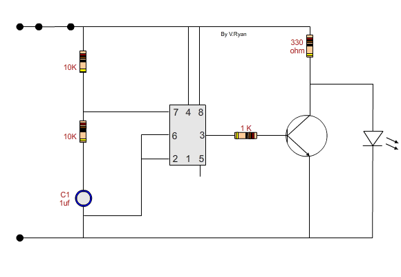
In an astable 555 circuit pins 2 and 6 are connected which means that the circuit will trigger itself continually until power is removed. The larger the value of the capacitor the longer the LED stays on and off. |
|
 |
|
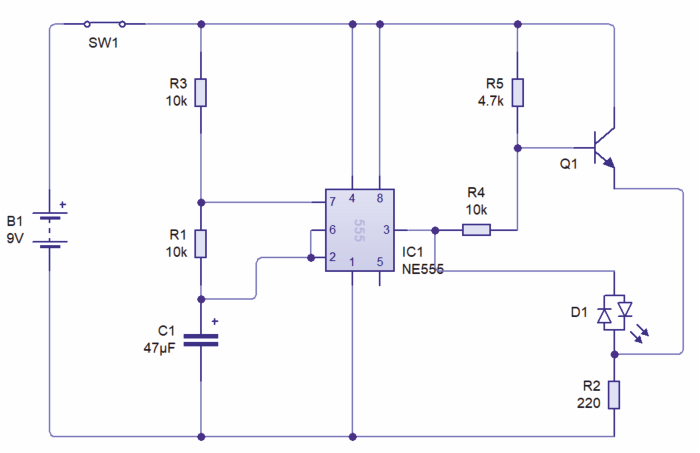
| DRIVING A BICOLOUR LED CIRCUIT WITH A 555 TIMER | |
| The circuit below drives a single bicolour LED. When the circuit is powered up, the LED alternatively flashes green and red. Pin three of the 555 timer, controls which anode of the bicolour LED, receives a positive voltage. The voltage from pin 3 of the 555 timer, pulses on and off, therefore the colour emitted by the LED alternates between green and red. |
|
| CIRCUIT WIZARD SOFTWARE | |
 |
|
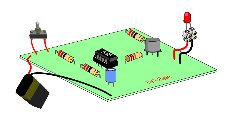
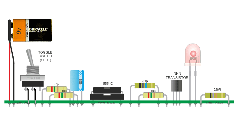
| PICTORIAL REPRESENTATION OF THE CIRCUIT SHOWN ABOVE | |
 |
|