| |
| CLICK HERE FOR INDEX PAGE |
| |
| GEAR DETAILS |
| V. Ryan © 2002 - 2016 |
| |
| PDF FILE - CLICK HERE FOR PRINTABLE WORKSHEET |
| |
 |
| |
|
|
| |
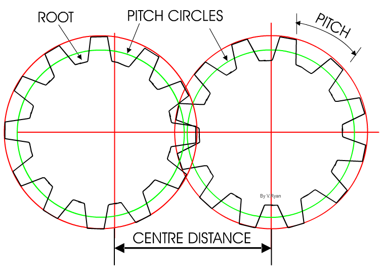
The gears above are known as spur gears. The circle marked in red shows the outer limit of the
teeth whilst the green circles are known as the pitch circles. The pitch circle of a gear is very important as it
is used by engineers to determine the shape of the teeth and the ratio
between gears (ratios will be explained later).
The pitch of a gear is the distance between
any point on one tooth and the same point on the next tooth.
The root is the bottom part of a gear
wheel. |
| |
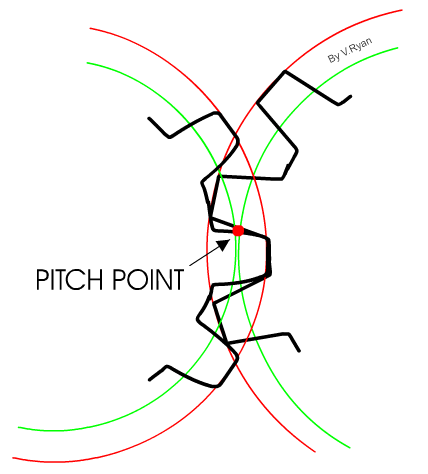
| The pitch point is the point where gear teeth
actually make contact with each other as they rotate. |
|
 |
| |
|
|
| |
Draw a single gear wheel and label the following:
The root, pitch circle, pitch, pitch point.
Draw two spur gears meshing together (Hint - do not draw all the teeth,
simply draw the gears with two circles representing each gear wheel -
see earlier example) |
| |
| CLICK HERE TO BACK TO GEARS INDEX |
| |
| |
| |