|
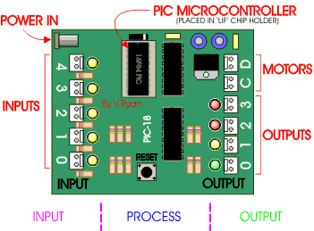
By now you have probably used ‘Logicator’ software to creat a flowsheet or program for a PIC microcontroller and tested it on the screen. The next stage is to download the program to a programmer and transfer it to PIC which fits into a project board - so that it can be tested as part of your practical project. The project board has inputs and outputs and these are identified on the diagram below. Switches and sensors can be connected to the inputs and motors, LEDs and circuits can be connected to the outputs. The advantage of using a project board compared to a smart box or similar interface is that it is small, light and can be transported easily. Also, it can be powered by 9v so that batteries can be used. |
|
|
|
|
|
|
|
|
The project board is designed for use with the 18 pin 16F84 PIC microcontroller. The project board has four inputs and four outputs plus two motor outputs. It can be powered by a 9 volt power supply or a battery snap can be connected. The PIC microcontroller is inserted in the LOW INSERT FORCE (LIF) chip holder as it is likely to be removed and replaced many times as the chip is reprogrammed. The RESET button is normally pressed to start the programmed PIC microcontroller working. |
|
|
|
|
|
|