|
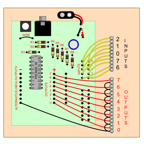
An neater alterative layout to the PICAXE 18 IC is seen below. The black, negative wires from the input side of the PCB have been replaced with one. This wire is screwed into a connector at the bottom right corner of the PCB. Small black wires ‘loop’ from one connector to another, completing the negative outputs connections. The red, positive wires are then screwed into the connectors. The circuit is ready to be programmed and used. |
|
 |
|
|
The circuit can then be fixed to a small piece of MDF to give it a firm base. This has the advantage that the PCB is held firmly and all the wires from the outputs and inputs on the PCB are also held in position. Consequently wires are unlikely to pulled from the PCB. |
|
|
|
|
| CLICK HERE FOR PIC-MICROCONTROLLER INDEX PAGE | |
|
|
|