|
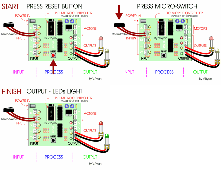
The project board below has been set up with a single input, the
micro-switch. There are two outputs, both are LEDs. When the PIC
microcontroller has been pushed into the LOW INSERT FORCE (LIF) chip holder
the reset button should be pressed to start the program. The PIC
microcontoller integrated circuit has been programmed to react when the
microswitch, connected to input 3, has been pressed. As it is pressed,
the signal created is detected by the program stored within the PIC
microcontroller which switches on the output LEDs. |
|
|
|
|
|
QUESTION: Draw a simplified diagram to represent the layout seen in the diagram above. Explain each stage - INPUT - PROCESS - OUTPUT. |
|
|
|
|
|
|
|
