| |
| CLICK HERE FOR INDEX PAGE |
| |
| SYSTEMS PREPARATION QUESTIONS 2007 - 6 |
| |
| V. Ryan © 2007-2017 |
| |
| PDF FILE - CLICK HERE FOR PRINTABLE WORKSHEET |
| |
| The diagrams below shows the plan view and front view
of an automatic sorting system. This sorts large, medium and small
packages so that they can be collected and placed in the correct carriage
of a train, for distribution to customers. |
| |
 |
| |
|
|
| |
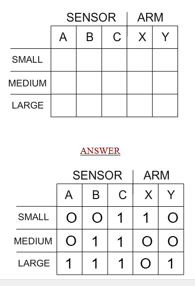
| The sensors detect the size of each package and are
connected to two control circuits. One circuit controls arm X and the
other arm Y. If the output of either of the control circuits is high
(logic 1) then the appropriate arm will swing to the position. |
| |
| 1. Complete the truth table below to show the logic
states of the three sensors that would give the correct outputs. The
sensors provide a ‘high’ (logic 1) if they detect a package and a’ low’
(logic 0) if no package is detected. |
| |
 |
| |
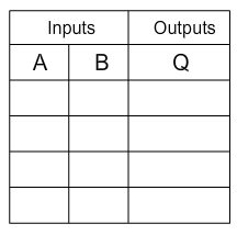
2. Part of each control circuit is composed of AND gates.
In the space below draw a diagram that represents an AND gate. Also,
complete the truth table (opposite) for a two input AND gate. |
|
 |
| |
|
|
| |
| YOUR DIAGRAM OF AND GATE: |
|
| ANSWERS |
| |
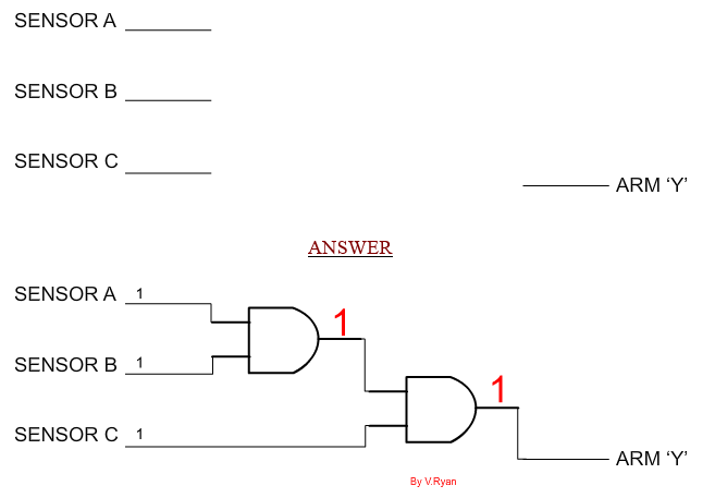
3. Draw a circuit diagram to show how two of these gates
could be used to control arm ‘Y’
The inputs from sensors A, B and C are already drawn along with the output
- arm ‘Y’ |
| |
 |
| |
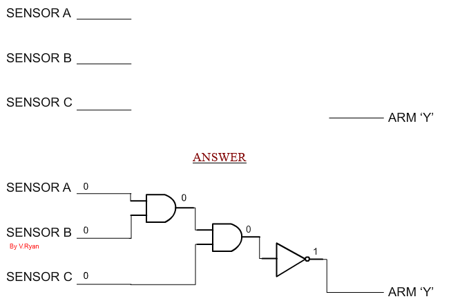
4. The control system has been found to be unreliable. It
has been modified by using sensors which give logic 0 when they detect a
package and logic 1 for NO package.
What type of gate could be added to your circuit (drawn above) to allow
for this change? |
| |
| |
| ANSWER |
| |
| NOT GATE (INVERTER GATE) |
| |
| 5. Draw the modified circuit in the
space below |
| |
 |
| |
| 6. Suggest a more cost effective modification to
the one shown above. |
| |
| |
| ANSWER |
| |
| A three input AND gate followed by a NOT gate would by
more efficient. Or a three input NAND gate. |
| |
|
|
| |
| CLICK HERE FOR ELECTRONICS INDEX PAGE |
| |