|
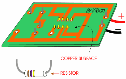
Electronic circuits in school and in industry are
normally produced through the use of PCBs (Printed Circuit Boards). The
boards are made from glass reinforced plastic with copper tracks in the
place of wires. Components are fitted to the boards by drilling holes
through the board. The copper tracks link the components together forming a
circuit. |
|
| The diagram below shows a resistor being positioned, ready for soldering. | |
|
|
|
|
|
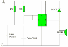
CIRCUIT DESIGN The circuit is usually designed on software such as ‘Crocodile Clips’. This allows you to test the circuit on the computer and correct any mistakes or make improvements. This saves time as there is no need to build the circuit with real components. |
|
PRINTED CIRCUIT BOARD LAYOUT The completed working circuit can then be exported to
software such as PCB Wizard which will automatically convert the circuit
diagram into a PCB mask. |
|
|
|
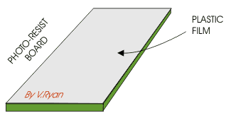
PHOTO-RESIST BOARD This a piece of glass reinforce plastic
is prepared.
One of the sides is copper clad and this copper has a photosensitive
coating. When the plastic film is peeled back this sensitive coating is
revealed. |