| CLICK HERE FOR INDEX PAGE |
| |
| BICOLOUR LEDs |
V.Ryan © 2022 |
| |
| PDF FILE - CLICK HERE FOR PRINTABLE WORKSHEET |
| CLICK HERE FOR POWERPOINT VERSION OF WORKSHEET |
| |
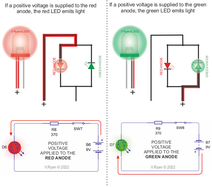
| A typical bicolour LED will light up in a one of two colours, depending on the current direction. It can be considered as two LEDs in one package. This type of LED has two terminals, with the LEDs connected side to side, anode to cathode. The terminal that is positive, has the LED that emits light. Therefore, bicolour LEDs are limited to two colours. |
| |
 |
| |
|
|
| |
| USING TWO BICOLOUR LEDs IN A CIRCUIT |
| |
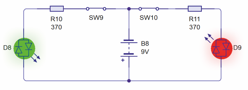
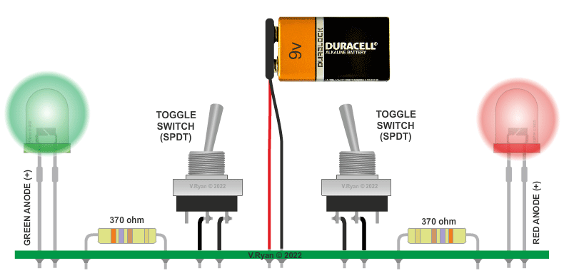
The circuit below, is basically two circuits in one. The 9V power source, supplies voltage to the right and left hand sides of the circuit, causing the bicolour LEDs to emit light, when the switches are ‘closed’. The red anode of one of the LEDs is connected to positive and green anode of the other LED. This means that one LED emits green light, whilst the other red light.
If only one light is required, only one of the switches needs to be closed.
|
| |
| CIRCUIT WIZARD SOFTWARE SIMULATION |
| |
 |
| |
| PICTORIAL REPRESENTATION OF THE TWO BICOLOUR LED CIRCUIT |
| |
 |
| |
|
|
| |
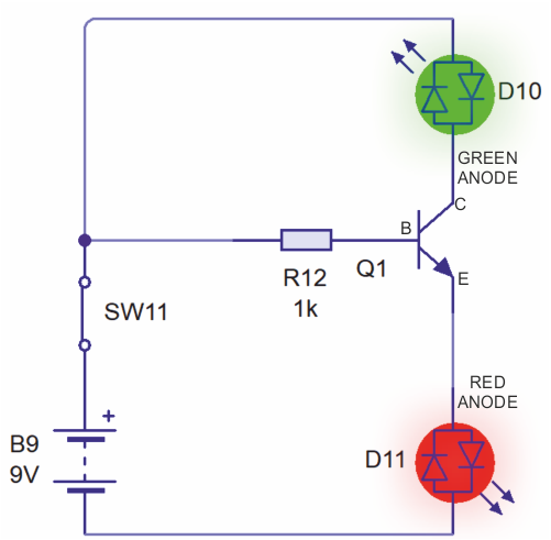
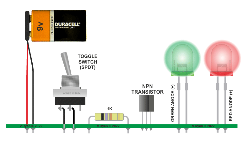
The circuit below has two bicolour LEDs, a toggle switch, npn transistor and a 1K resistor.
When the circuit is powered, both LEDs light, one green and the other red.
With one of the LEDs, the green anode is connected to positive voltage. The other LED has its red anode connected to positive.
A small current or voltage at the base (B) of the transistor, allows a larger voltage to flow through the other two leads (from the collector (C) to the emitter (E)). This allows both LEDs to light. |
| |
| CIRCUIT WIZARD SOFFTWARE SIMULATION |
| |
 |
| |
| PISTORIAL REPRESENTATION OF THE CIRCUIT SHOWN ABOVE |
| |
 |
| |
|
|
| DRIVING A BICOLOUR LED CIRCUIT WITH A 555 TIMER |
| |
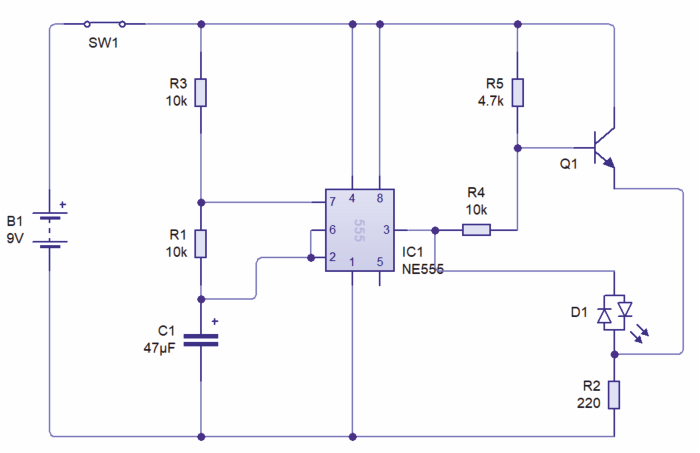
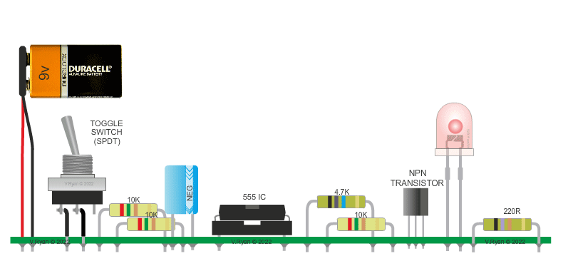
The circuit below drives a single bicolour LED. When the circuit is powered up, the LED alternatively flashes green and red. (Click here for more detail on 555 timers).
Pin three of the 555 timer, controls which anode of the bicolour LED, receives a positive voltage. The voltage from pin 3 of the 555 timer, pulses on and off, therefore the colour emitted by the LED alternates between green and red. |
| |
| CIRCUIT WIZARD SOFTWARE CIRCUIT LAYOUT |
| |
 |
| |
| PICTORIAL REPRESENTATION OF THE CIRCUIT |
| |
 |
| |
| CLICK HERE FOR ELECTRONICS INDEX PAGE |
| |
|
| |
|